
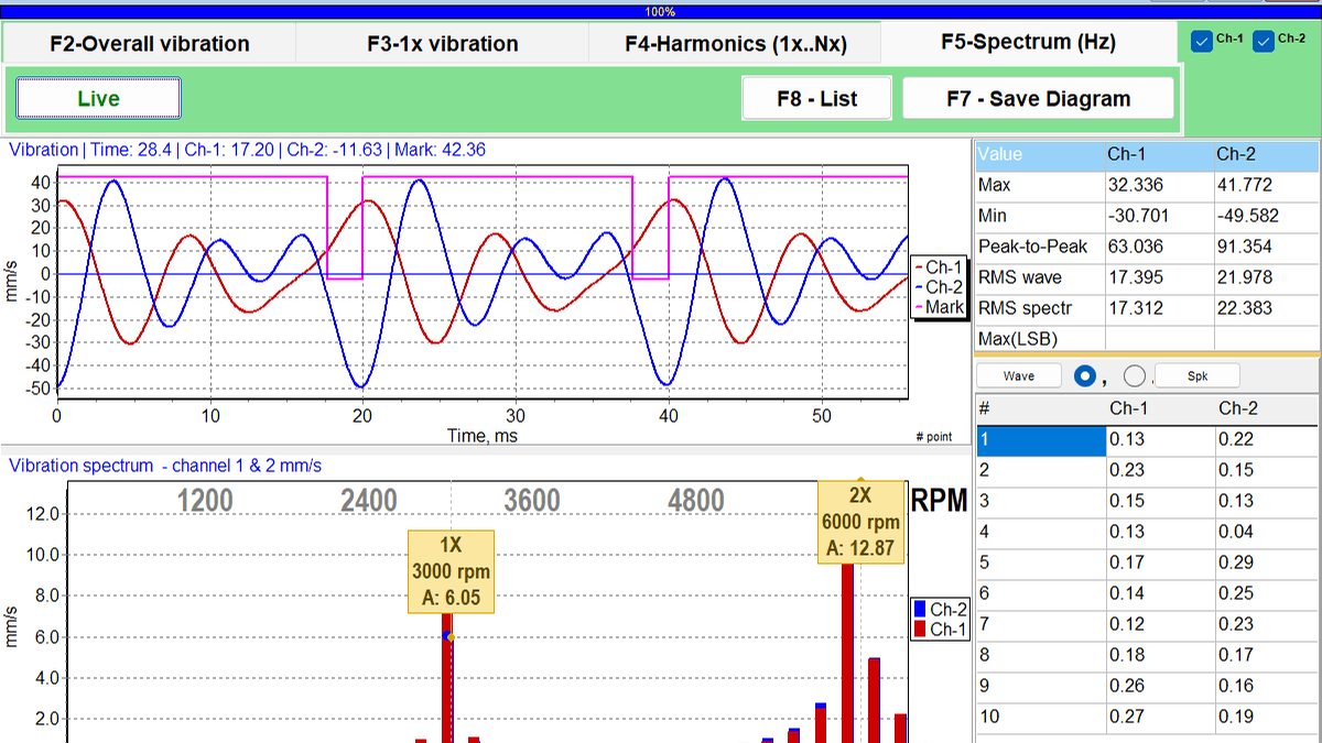
A rotating machine warns you before it fails. That warning is usually vibration, and read correctly it does not just say "there is a problem"; it tells you what the problem is. Imbalance, misalignment, looseness and bearing damage leave different signatures in the vibration spectrum. In this post we look at telling those signatures apart.
What are we measuring?
Vibration is expressed in three quantities, and which one you use depends on the fault you are looking for.
| Quantity | Unit | Sensitive at which frequency | Used for |
|---|---|---|---|
| Displacement | µm | Low (< 10 Hz) | Slow machines, shaft runout |
| Velocity | mm/s | Medium (10–1000 Hz) | General-purpose diagnosis |
| Acceleration | g | High (> 1000 Hz) | Bearing and gear damage |
For routine monitoring, velocity (mm/s RMS) is used; imbalance, misalignment and looseness show up in this band. Early bearing damage, however, appears at high frequency and needs acceleration measurement.
Measurement points and directions
The measurement is taken at the point closest to the bearing load, that is, on the bearing housing, directly in line with the bearing if possible. Measurements taken over paint, sheet-metal covers or guards are misleading.
The spectrum: fault signatures
The raw vibration signal on its own says little. When you split it into its frequency components (FFT), you see how much energy there is at which frequency. All the diagnosis is done here.
The reference point is the 1× running speed frequency: the machine's revolutions per second. For a motor turning at 1500 rpm, 1500 ÷ 60 = 25 Hz. Other peaks are read as multiples of this.
Imbalance
In the spectrum, the 1× running speed frequency dominates on its own and the other harmonics are small. The radial direction (vertical and horizontal) is high and axial is low. If the difference between vertical and horizontal is large, the base is also flexible.
The cause is usually dirt built up on the blades, a balance weight that has come off or a worn impeller. It is the most common fault in fans.
Misalignment
If the 2× running speed frequency dominates, and especially if axial vibration is more than half the radial, the alignment is off. This is exactly the signature we mentioned in the alignment post.
Angular misalignment raises the axial value markedly; parallel misalignment brings out the radial 2× component. If both are present, both show.
Mechanical looseness
The spectrum shows many harmonics in a row: 1×, 2×, 3×, 4×, 5× and so on. Sometimes half-order components such as 0.5× appear too. This shows that something is moving freely.
A loose foundation bolt, a cracked base, a worn bearing seat or the bearing turning in its seat are typical causes. The soft foot from the alignment post also belongs in this group.
Bearing damage
A bearing fault appears in a high-frequency zone that is not proportional to running speed. The damaged element makes a certain number of contacts per revolution, and that number depends on the bearing's geometry. It is not a whole number, so it does not show up as a multiple of 1×.
There are four characteristic frequencies: outer race damage (BPFO), inner race damage (BPFI), rolling element damage (BSF) and cage damage (FTF). Which frequency stands out tells you where the damage is; these values for a bearing can be found in the catalogue.
What matters in practice is this: early bearing damage hardly shows at all in velocity (mm/s) measurements. Catching it needs acceleration (g) measurement or envelope analysis. If you only track mm/s, you will notice a bearing fault only very late.
When should you act?
To know whether the value you measured is high, you need a scale. ISO 10816 classifies machines by size and mounting and defines four zones.
| Zone | Small machine (15–75 kW) | Medium/large, rigid base | Meaning |
|---|---|---|---|
| A | ≤ 1.4 mm/s | ≤ 2.3 mm/s | New machine level |
| B | 1,4 – 2,8 | 2,3 – 4,5 | Fit for unrestricted operation |
| C | 2,8 – 4,5 | 4,5 – 7,1 | Acceptable for a short time; plan action |
| D | > 4,5 | > 7,1 | Causing damage; stop it |
These values are in velocity RMS and are only a rough framework; check the standard's table for your machine's actual class.
More important than the absolute value is the trend. A machine sitting steady at 3.0 mm/s is less worrying than one that went from 1.2 to 2.4 in a month. So keep regular records rather than taking one-off measurements.
Making the measurement reliable
- Take every measurement at the same point. Mark the points permanently, or even glue on a measurement stud.
- The probe must be perpendicular to the surface; a probe held at an angle reads low.
- Do not measure over paint, rust or dirt; high-frequency components are damped.
- The machine should be in its normal operating condition: same load, same speed, warmed up.
- A magnetic probe weakens at high frequency; for bearing monitoring prefer a contact probe or a permanent sensor.
- Record the measurement. A record kept with date, load and temperature is your only source for trend analysis.
Diagnosis flow
- Measure at four points in three directions and record the values.
- Find which point and direction has the highest value.
- If axial is more than half of radial, start looking for misalignment.
- Look at the spectrum: 1×, 2×, many harmonics or a high-frequency cluster?
- Match it against the table and narrow down the likely cause.
- Measure again after the fix; if it has not dropped, the diagnosis was wrong.
Quick checklist
- Use mm/s for routine monitoring and acceleration or envelope analysis for bearings.
- Mark the points and always measure in the same place.
- 1× dominant → imbalance; balance it.
- 2× dominant + axial high → misalignment; redo the alignment.
- Many harmonics → looseness; check bolts and seats.
- High frequency not proportional to speed → bearing; planned replacement.
- Look at the trend, not the absolute value.
- After every fix, repeat the measurement to confirm.
Vibration monitoring does not need expensive equipment; even a simple handheld meter and a regularly kept log catch a large share of faults in advance. The real value is not in the device but in repeating the measurement under the same conditions and following the trend. The machine is telling you; the point is to set up a routine to listen.
Frequently asked questions
What unit is vibration measured in?
Velocity (mm/s RMS) is used for overall machine condition, and ISO limits are given in it. For high-frequency faults such as bearings and gears, acceleration (g) and envelope measurement warn earlier.
How are unbalance and misalignment told apart in the spectrum?
Unbalance usually shows a clear peak at 1× running speed in the radial direction. Misalignment brings out a 2× component and axial vibration; phase difference across the coupling is also a clue.
How often should measurements be taken?
Monthly on critical machines and quarterly on others is usually enough. The real value is in the trend of readings taken at the same point under the same conditions, not in a single reading.
Sources
This article is a compilation based on the sources below and personal experience; its assessments are opinions. In practice, the manufacturer's official documentation and applicable regulations take precedence.
- ISO 20816-1 — Mechanical vibration: Measurement and evaluation of machine vibration
- ISO 10816-3 — Industrial machines with nominal power above 15 kW
- ISO 13373-1 — Condition monitoring and diagnostics of machines: Vibration condition monitoring
Comment
No comments yet. Be the first to comment!
Leave a comment