
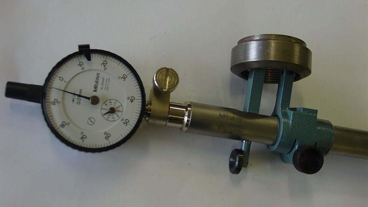
If a bearing fails long before its catalogue life, check the alignment between the shafts and the coupling before blaming the bearing. Misalignment puts extra load on the bearing and seal on every revolution; that load never stops, it lasts as long as the machine runs. In most places where people say "we keep eating bearings", the problem is not the bearing but the alignment.
What is misalignment, and what types are there?
Misalignment means that the rotation axes of the driving (motor) shaft and the driven (pump, gearbox) shaft do not coincide. It has two basic forms, and in the field both are usually present.
There is a third case that is easily missed: axial misalignment, meaning the gap between the coupling halves is outside the manufacturer's tolerance. If it is too narrow, thermal expansion pushes the shaft and the bearing ends up under axial load; if it is too wide, the flexible element is constantly stretched.
What does misalignment cost?
The cost of misalignment is not only bearings. The knock-on effects are:
- Bearing life shortens. In the L10 formula in the bearing post the exponent was 3; because misalignment increases the load, the life drops fast.
- Seals leak early. Because the shaft wobbles on every turn, the seal lip wears unevenly.
- Energy consumption rises. A misaligned coupling keeps deforming as it turns, and that work turns into heat.
- The coupling element (rubber, spider, sleeve) tears much earlier than normal.
- Vibration increases and loosens the bolted joints around it.
Using a flexible coupling does not excuse misalignment. A flexible coupling is there to tolerate the small errors left after installation and thermal movement, not to ignore the error. In a misaligned system, a flexible coupling only moves the failure: the coupling element dies instead of the bearing.
Before aligning: preliminary checks
Skipping these steps before setting up the dial indicator or laser leads to hours of wasted effort.
Soft foot
If one of a motor's four feet does not sit fully on the base, the frame twists when you tighten the bolt and your alignment is ruined. This is called soft foot, and it must be fixed before you start aligning.
Detecting it is simple: place the dial indicator on the foot, loosen that foot's bolt and read the movement. If it lifts by more than 0.05 mm, there is soft foot; fill it with a shim of the right thickness.
Other checks
- Clean the base and rail surfaces; a single speck of dirt means a 0.1 mm error.
- Throw away rusty or dented shims. Do not stack more than four shims; they act like a spring.
- Remove the coupling bolts so the two shafts can turn independently.
- If the shaft ends have axial play (float), keep pushing the shaft in the same direction throughout the measurement.
- Check for pipe strain: if the pump moves when you loosen the pump flange bolts, the pipework is pulling on the pump. That ruins the alignment during operation.
Aligning with a dial indicator
Without a laser tool, you can get reliable results with two dial indicators. The most common method is the reverse dial (rim–face) method.
How do you validate the readings?
There is a practical way to tell whether the measurement is valid: the sums of opposite readings must be equal. That is, the readings at 3 and 9 must add up to the same as those at 12 and 6. Since you zeroed at 12, this simply becomes:
reading(3) + reading(9) = reading(6)If it does not add up, the measurement is not reliable. The cause is usually one of these: the bracket is flexing, the indicator tip is slipping, the shaft has axial play, or the coupling bolts have not been fully removed.
Direction of correction
When interpreting the readings, remember this rule: if the indicator tip is reading a surface, half the reading is the actual misalignment. As the shaft turns, the error shows up in both the plus and minus directions; the total runout is twice the actual offset.
Vertical correction is made with shims, horizontal correction by moving the motor sideways. Correct the angular misalignment first, then the parallel; if you work in the reverse order, each correction undoes the other and you go round in circles.
Tolerance: how precise is enough?
No alignment is perfect; the aim is to get within an acceptable range. The tolerance depends on speed: the faster the machine turns, the more damage the same misalignment does.
| Speed (rpm) | Parallel misalignment | Angular misalignment (per 100 mm) |
|---|---|---|
| 600–900 | 0.09 mm | 0.09 mm |
| 900–1200 | 0.06 mm | 0.07 mm |
| 1200–1800 | 0.05 mm | 0.05 mm |
| 1800–3600 | 0.03 mm | 0.03 mm |
| 3600–7200 | 0.02 mm | 0.02 mm |
These values are the generally accepted "excellent" range; if the manufacturer's catalogue gives a looser limit, you can use that. Note how small the figures in the table are: on a pump turning at 1500 rpm, 0.05 mm, about half the thickness of a hair, is the limit. That is why aligning by eye or with a straightedge is not enough.
Thermal growth: align cold, run hot
You align the machine cold, but it heats up and grows when it runs. An electric motor expands by its foot height at operating temperature; it may look like a few hundredths of a millimetre, but by the tolerance table above it is a serious amount.
On machines that run hot (steam pumps, furnace fans, compressors), the cold alignment is deliberately left slightly off the target value; when the machine warms up, it expands into the right position. This value is given in the manufacturer's documents and is not applied by guesswork.
A practical way to check: align the machine, run it until it reaches operating temperature, stop it and measure again immediately. The difference is your thermal growth; you allow for it at the next alignment.
How do you know the alignment has gone?
You do not need to take the alignment apart every month; the machine will tell you.
- If the 2× running speed frequency dominates the vibration spectrum, it is a classic sign of misalignment. If 1× dominates, look for imbalance.
- If axial vibration is more than half the radial vibration, angular misalignment is very likely.
- Heat around the coupling shows that the flexible element is constantly deforming.
- If you see rubber dust or tears on the coupling element, misalignment is eating it.
- If bearing failures keep coming from the same housing, measure the alignment before changing bearing brands.
Quick checklist
- Fix soft foot before aligning, not after.
- Clean the base, shims and foot surfaces; do not stack more than four shims.
- Remove the coupling bolts and check for pipe strain.
- Zero the dial indicator at 12; read at 3, 6 and 9. If
3 + 9 = 6does not hold, repeat the measurement. - Correct angular misalignment first, then parallel.
- Choose the tolerance by speed; above 1500 rpm, do not exceed 0.05 mm.
- Allow for thermal growth on machines that run hot.
- When finished, tighten the bolts to the torque value and take the final measurement after tightening; tightening can upset the alignment.
Alignment is one of the highest-return jobs in maintenance. An hour of proper alignment cuts off months of repeated bearing and seal failures from the start. And it costs nothing in spare parts; it only needs patience and the right order of work.
Frequently asked questions
If a flexible coupling tolerates misalignment, why align?
A flexible coupling carries misalignment at the cost of its own life, and the extra forces load the bearings and seals. What the coupling allows is not what lets the machine run for a long time.
Laser alignment or dial indicators?
Both give good results when done correctly. Laser is faster and has no bracket sag over long spans; dial indicators are cheaper but bracket sag must be measured and accounted for.
How often should alignment be checked?
After installation and after the first few weeks of running, then whenever symptoms appear such as rising vibration, coupling wear or bearing temperature. Yearly checks are common on critical machines.
Sources
This article is a compilation based on the sources below and personal experience; its assessments are opinions. In practice, the manufacturer's official documentation and applicable regulations take precedence.
- ANSI/ASA S2.75 Part 1 — Shaft Alignment Methodology
- Piotrowski, J. — Shaft Alignment Handbook, CRC Press
Comment
No comments yet. Be the first to comment!
Leave a comment