
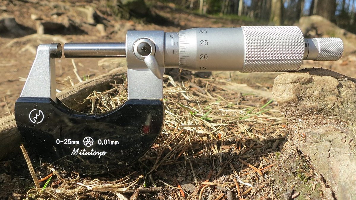
Machining, manufacturing and engineering often call for measurements to a hundredth, or even a thousandth, of a millimetre. The micrometer is a precision measuring instrument developed for exactly this need. Linking the rotation of a screw to linear movement, it is used in analogue versions with 0.01 mm resolution and in vernier or digital versions with 0.001 mm resolution.
What Is a Micrometer?
A micrometer works by turning the rotation of a precision screw on the spindle into linear movement. The screw pitch is machined to exactly 0.5 mm, so one full turn of the thimble moves the spindle 0.5 mm. The 50 divisions on the thimble split that 0.5 mm into equal parts: each division means 0.01 mm.
| Model | Resolution | Use |
|---|---|---|
| Standard Analogue | 0.01 mm | General workshop measurement |
| Analogue with Vernier | 0.001 mm | Precision die and tool measurement |
| Digital | 0.001 mm | SPC data collection, fast reading |
Each micrometer measures only a 25 mm range: they are sold in sets such as 0–25 mm, 25–50 mm and 50–75 mm. This limit prevents the error that would build up as the screw got longer.
A Short History
The first designs to use the screw principle for precise measurement go back to 17th-century astronomers; William Gascoigne and Adrien Auzout developed the micrometer screw to measure star separations in telescopes. The modern hand micrometer, however, was founded on Jean-Louis Palmer's 1848 French patent: the C-frame and rotating thimble came together for the first time in this design. Brown & Sharpe took it into industrial production in 1867, and makers such as Mitutoyo, Starrett and Mahr improved its precision throughout the 20th century. Today, digital models that send data to SPC software over Bluetooth are standard.
Parts and What They Do
- Frame: The C-shaped main body, made of cast or forged steel. The plastic or epoxy insulator in the middle reduces thermal expansion from your hand.
- Anvil: The fixed measuring face. Tungsten carbide tipped; surface roughness below Ra 0.05 µm.
- Spindle: The moving measuring face. It travels on a precision screw with a 0.5 mm pitch.
- Sleeve / Barrel: Carries the reference line with the millimetre and 0.5 mm divisions.
- Thimble: The 50-division scale; it turns with the spindle. Each division = 0.01 mm.
- Lock Nut: Locks the spindle so the reading does not shift when you pull the tool off the workpiece.
- Ratchet Stop: Applies a constant, repeatable measuring force (≈7 N). It is the most important part for preventing overtightening.
- Vernier Scale: Only on some models; 5 extra divisions on the sleeve allow 0.001 mm readings.
The heat insulator in the middle of the frame looks small but matters: if a micrometer is held in the hand for a long time, the metal expands and the reading can be wrong. Use heat-resistant gloves for long series of measurements.
Types of Micrometer
| Type | English Name | Purpose | Typical Range |
|---|---|---|---|
| Outside Micrometer | Outside Micrometer | Outside diameter and thickness of shafts, pins and plates | 0–25 mm, 25–50 mm… |
| Inside Micrometer | Inside Micrometer | Bore diameter; extends with extension rods | 5–30 mm + |
| Depth Micrometer | Depth Micrometer | Depth of blind holes, grooves and steps | 0–25, 0–50 mm |
| Screw Thread Micrometer | Screw Thread Micrometer | Pitch diameter of a thread | 0–25 mm |
| Tube Wall Thickness | Tube Micrometer | Wall thickness of tubes and cylinders | 0–25 mm |
| Digital Micrometer | Digital Micrometer | Fast reading, data logging, mm/inch conversion | 0.001 mm resolution |
| V-Anvil Micrometer | V-Anvil Micrometer | Diameter of 3- and 5-flute cutting tools | 0–25 mm |
| Point Micrometer | Point Micrometer | Measuring deep grooves and narrow gaps | 0–25 mm |
How to Read the Scale
An analogue micrometer is read in three stages, and the results are added together.
Step 1: Sleeve (Barrel) Scale
Each division above the reference line on the sleeve is 1 mm, and each division below it is 0.5 mm. Read the last line visible closest to the left edge of the thimble.
Step 2: Thimble Scale
On the thimble, numbered 0 to 50, read the division that lines up with the reference line. Each division = 0.01 mm.
Step 3: Vernier (for 0.001 mm)
Vernier models only: find which of the 5 extra divisions on the sleeve lines up with a thimble division; add that value × 0.001 mm to the total.
Example reading: 7.23 mm
Sleeve whole mm: 7.00
0.5 mm division not visible: 0.00
Thimble division 23: 0.23
Total: 7.00 + 0.00 + 0.23 = 7.23 mm
Always read the scale straight on, at eye level. Looking at an angle causes parallax error and the wrong division can appear aligned.
Using It Step by Step
- Cleaning: Wipe the anvil and spindle faces with a clean cloth or lens tissue. Clean the measuring surface of the workpiece too; a single chip can cause an error of tens of micrometres.
- Zero check: Bring the spindle up to the anvil and close it with the ratchet. The "0" on the thimble must line up exactly with the reference line. If not, reset the zero.
- Opening the spindle: Turn the thimble back to leave a gap larger than the workpiece.
- Positioning: Centre the workpiece between anvil and spindle. Tilted contact makes the reading too large.
- Closing with the ratchet: Close the spindle only with the ratchet. Stop when it clicks; that is the sign of the right force. Tightening with the thimble damages the workpiece and leads to a wrong reading.
- Locking: Turn the lock nut to fix the spindle so it does not shift as you pull the tool away.
- Reading: Read sleeve → thimble → (if fitted) vernier in that order, and add them up.
- Recording: Note the value, release the lock and back the spindle off.
Measuring the same point 3 times and taking the average checks both your positioning and the consistency of the ratchet.
Calibration and Care
Daily Zero Check
Check zero before every use. For micrometers of 25 mm and above, a setting standard of the right length is used. If the zero error is more than ±4 divisions, send it for service.
Periodic Check
Once a month, check the whole range with NIST/TÜRKAK-traceable gauge blocks (at 0, 12.5 and 25 mm). A deviation of more than 0.01 mm means it needs calibrating.
Storage and Care
- After use, wipe all surfaces and apply a thin coat of instrument oil.
- Do not store it with the measuring faces touching; leave them slightly apart.
- Keep it in its protective case, in a dry place free of vibration.
- Keep it away from sunlight and heat sources.
- After a drop, always check the calibration.
- In industrial use, send it to an ISO 17025 accredited laboratory at least once a year.
Common Mistakes
| Error | Cause and Effect |
|---|---|
| Tightening with the thimble | Using the thimble instead of the ratchet applies 3–5 times more force; it damages the workpiece and the reading comes out small. |
| Dirty surfaces | Chips or dust increase the gap between anvil and spindle; wipe before every measurement. |
| Thermal expansion | Steel expands 11.7 µm/m·°C; holding a 200 mm part in your hand for 5 minutes can cause an error of ~12 µm. |
| Tilted contact | Contact that is not square to the anvil/spindle faces gives a reading larger than the true value. |
| Skipping the zero check | Heat, humidity and use cause zero drift; a daily check is essential. |
| Parallax error | Reading the scale at an angle makes the wrong division appear aligned; always keep your eye square to it. |
Frequently asked questions
What is the difference between a micrometer and a caliper?
A standard digital caliper resolves 0.01 mm, a micrometer 0.01 mm and 0.001 mm with a vernier. Because it uses a screw and a ratchet for constant force, a micrometer is more precise but has a narrow range (usually 25 mm).
Why use the ratchet on a micrometer?
The ratchet keeps the measuring force the same every time. Tightening the thimble directly by hand varies the force from person to person and shifts the reading by a few microns.
How often should the zero be checked?
Check zero before every use with clean measuring faces. Micrometers larger than 25 mm use a setting standard for this.
Sources
This article is a compilation based on the sources below and personal experience; its assessments are opinions. In practice, the manufacturer's official documentation and applicable regulations take precedence.
- ISO 3611 — GPS: Dimensional measuring equipment — Micrometers for external measurements
- Mitutoyo — micrometer usage guides
Comment
No comments yet. Be the first to comment!
Leave a comment